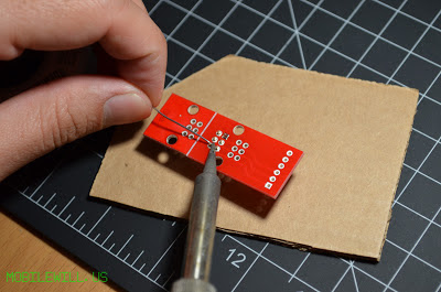
I couldn't pass it up as I program many boards without soldering headers. By the following week I had the kit in hands, ready to solder up!
This kit is great. It's easy to solder together by following the SFE assembly video. Here are a couple of pictures of me assembling.
You can pick one up here: https://www.sparkfun.com/products/11591, at a great price. It's definitely worth it!


Heh .. typical Sparkfun, $10+S/H+$1/pogo pin - good price? you're kidding right?
ReplyDeleteWhat I did was I just used some jumper wire to attach pogo pins for a simple ISP connector without the bulkiness of such adapter (not even sure how you'd use that in tight spaces, let alone see what you do).
See my step by step for making such jogs here:
http://lowpowerlab.com/blog/2013/06/27/illustrated-guide-to-making-simple-jigs-for-programming-and-testing/
The pins are included. Its not a bad price. I know from experience costs add up even for cheap items. What I have been doing is just sticking headers in the ISP connector and holding them at a angle. Too bad they don't make a ribbon cable connector with pogo pins bult in. I actually have a tab open with that exact link from the other day. I do use pogo pins for testing the USB Tester OLED backpack. I will read the link, I haven't had a chance to yet.
DeleteOh and by the way, if you don't enforce the pogos where they have the notch (hard to see in these pics but it's there) they will tend to break after a while, the SFE board didn't account for something as trivial as that, they should have made the height such that the notch is sandwiched inside the thickness of the second PCB.
ReplyDelete