Monday, December 9, 2013

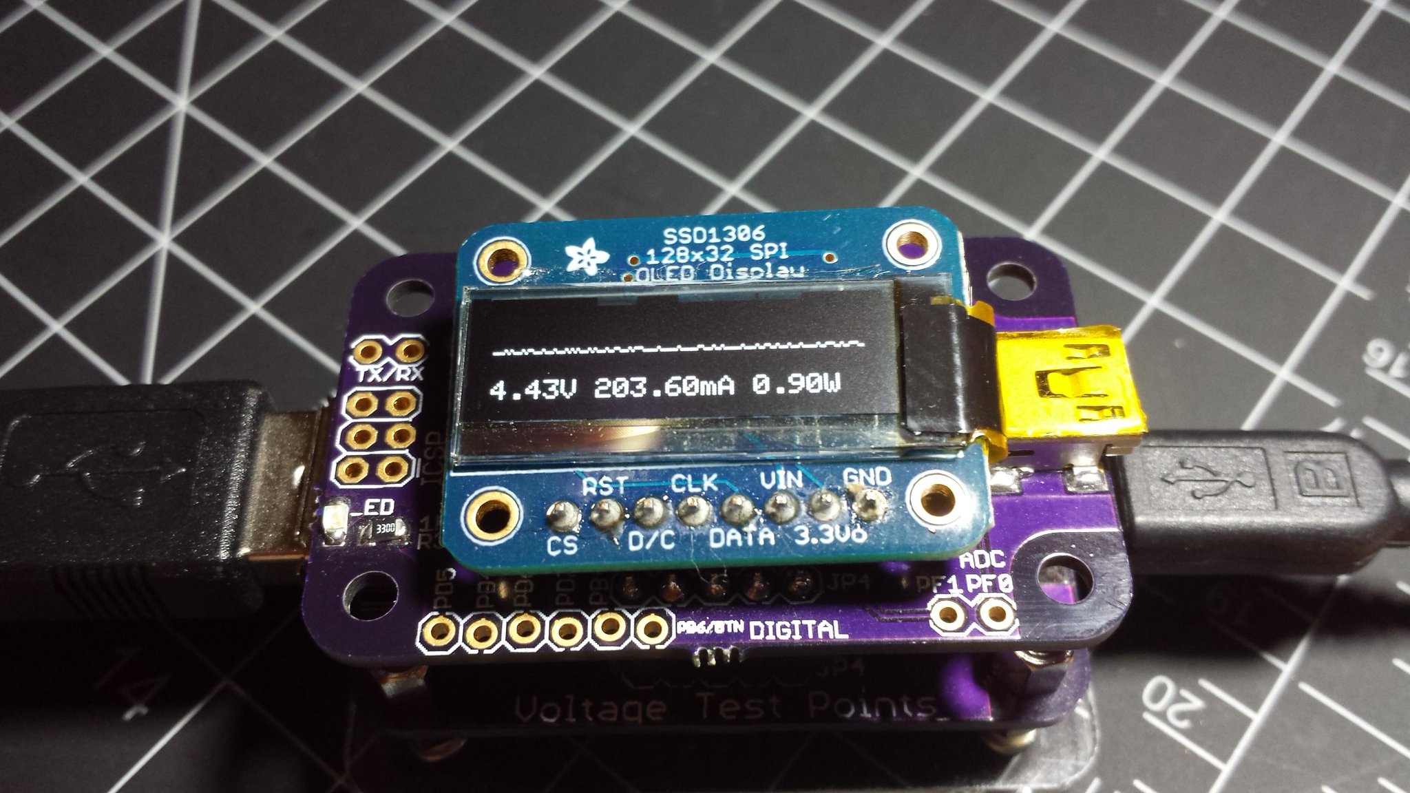
New Product: USB Tester 2.0 Bundle!

After months of development, the USB Tester 2.0 Bundle has arrived!


Currently available on Tindie and soon on Friedcircuits.us

USB Tester Bundle 2.0
USB Tester Backpack 2.0

The bundle includes both a new version of the Backpack and USB Tester. At this time, the new USB Tester is only available with the bundle.


New on Backpack
  • Micro USB
  • Button Location on the front left
  • 128x64 OLED Display (Double height of the 1.x version, easier to source)
  • Voltage monitoring of the USB Data lines
  • Easier access to almost all the extra GPIO’s


New on USB Tester
  • Micro USB
  • Separated voltage test points (Easier to attach test clips and avoid misplacing jumper)
  • Better labeling
  • Standard Dual Banana spacing 0.75in
  • Standard test probe sized test points


New Firmware Features (Will be available for 1.x version)
  • Peaks
  • mWh and mAh tracking
  • Big Readout Display
  • JSON for serial communications


Updated Java App (Beta)
  • Implemented JSON over serial
  • Will save as CSV
  • Add display of new data values
  • Working on graphing some of the new data


We’d like to thank Ed for all of his help and contributions.
http://www.aerodynes.fr/2013/09/08/fried-circuits-tester-multiscreen-and-energy-measurement/

Saturday, December 7, 2013

Angstrom Yocto 1.4 from Source

Going down the ROS road has been a long one. Full of hair pulling (if I had any) but also a huge learning experience now that it is working. Due to some of the requirements for mjpeg-server I had to compile Angstrom from source so that I can use the branch for Yocto 1.4. In turn this has lead to having to compile other components like the WiFi driver.

Compiling from source isn't too bad as it uses the same Bitbake process used for recipes. The hard part is flashing the SD Card and then flashing the eMMC. I am not sure if  I did it the "correct" way but in the end it worked. This is how I did it...

BBB: Getting Setup, Updating, NTP, WiFi

This post comes after having a few issues and deciding to redo my BeagleBone Black.Unlike the Raspberry Pi, there are few things you need to do, like loading the latest image, WiFi, and NTP.

Your Beaglebone Black may not come with the latest image but after flashing there are still updates by running the opkg update and opkg upgrade. This takes a long time to run. Once complete, the SSH session will be disconnected and you can power cycle. If you have connection errors it's a problem with DNS and you can add the feed URL to the hosts files. https://groups.google.com/forum/#!topic/beagleboard/Kyq1NQOFSns Running an upgrade is optional; it will run fine without it. 

Download the latest image:
http://downloads.angstrom-distribution.org/demo/beaglebone/

Download the one with BBB-eMMC-flash-XXX.img.xz

Sunday, December 1, 2013

Weekend Harmony 720 Repair


A few days, weeks ago our Logitech Harmony 720 remote had some issues. It seems that the interface and buttons were working but not transmitting to any device. Over Thanksgiving weekend I got a chance to take it apart to see what was going on. During the IR Camera, test I was able to confirm the IR LEDs where not emitting at all.

After a quick Google search, it looks like this is a common issue. It could be from the heat generated while charging. To me, it sounds like an engineering flaw. But I have to admit this remote lasted a long time and it was purchased from eBay. It's probably been at least 3+ years.

Harmony 720 Parts

Monday, November 18, 2013

FriedCircuits now on InMojo.com

I recently heard about iNMOJO.com. Similar to Tindie, so I decided to give it a try. Currently just the USB Tester is listed.


http://www.inmojo.com/store/friedcircuits/item/usb-tester/


Let me know in the comments if you have heard or had any experiences (good or bad) with inmojo.com.

Sunday, November 17, 2013

Twitter Bootstrap and ROS

Working on the BeagleBone Black and ROS, I started playing with the Twitter Bootstrap framework. Its a combination of CSS and Javascript libraries that make is much easier to create a website from scratch. I had heard of it and seen a few projects but never dived into it. With the new robot running ROS which has a websocket interface, I ended up trying Bootstrap. Here are few resources I used to get started plus a few screenhots of what I am working on. Once it is in a usable state I will post it on Github and a guide on how to use it. In the meantime I will try to post what I can.

Get Bootstrap: http://getbootstrap.com/
     Good getting started resources

BBB: WebCam Streaming

After figuring out the Raspberry Pi camera module and getting MJPG-Streamer working I decided to try it on the BBB(BeagleBone Black). This should be easier as you are working with USB vs the RPi camera module which isn't full developed.  Thanks to Warren I already had a Logitech C210 camera I use for the Adaruit show and tells and video chating with family.  Any UVC camera should work, you can check out this list: http://en.wikipedia.org/wiki/List_of_USB_video_class_devices.

Fastest way to check is to plug it in and see if the system sees it as a camera.

# lsusb - will show all USB devices on the bus. This doesn't mean it has the driver.

# ls /dev/  - will list all the devices in the system that have drivers loaded and are ready to use. Look for video0. If it is there you should be ready to go.

Now we just need to download mjpg-streamer. I used part of this guide: http://shrkey.com/installing-mjpg-streamer-on-beaglebone-black/.

Pretty simple compared to the time I spent on the RPi since I wanted to do it without writing a file everytime.

cd ~
su
opkg install subversion libjpeg-dev imagemagick
exit
svn checkout svn://svn.code.sf.net/p/mjpg-streamer/code/ mjpg-streamer-code
cd mjpg-streamer-code/mjpg-streamer-experimental
make
I tried both the experimental and the stable release and both worked fine.

Finally to run it with the full web interface:

./mjpg_streamer -i "./input_uvc.so" -o "./output_http.so -w ./www"

Then you can connect to it via your web browser:

http://beagleboneIP:8080/

You can use VLC as a streaming client but there is a much greater delay due to buffering. This might be adjustable, haven't checked yet. VLC was showing mostly green instead of the video but VLC worked with RPi.

There are a bunch of other options you can find here: <link>

I am using -f 5 to limit FPS to 5. Should help on slower connections but affects the delay.

Using a USB webcam works much better for realtime streaming vs the RPi camera module. I am sure if you used a USB webcam on the RPi it would be better as well.

Saturday, November 16, 2013

Adruino and working with limited memory

Check out this great post about how Arduino memory works and how to work with limited memory. This includes tips of ways to trim the fat from your program.


http://learn.adafruit.com/memories-of-an-arduino

BBB: Adventures in ROS - Cross Compiling and Recipes

Previously I setup ROS on the BeagleBone Black and installed Angstrom build environment on Ubuntu x86 so I can compile for ARM. Now that the base is setup we can add the Beagle-Ros layer and try cross compiling a recipe with Bitbake. Wait, what... what is layers and baking recipes you speak of, are we cooking?

Since we can't compile directly on the BBB we have to do it on a x86 system. But we have to tell the compiler the architecture we want and how to package it up into a IPK that we can install on the BBB. The IPK needs to have all the right parts to make a ROS package. But you can test using just python scripts without make the compiled package.

The base install uses OpenEmbedded then there are layers on top of that to add functionality such as a meta ROS layer. This layer provides all the sources files to compile ROS. This should be in the

setup-scripts\sources\meta-ros

On top of that Victor from Beagle-Ros.org created a layer for the Beaglebone parts. Which include recipes for some of the common sensors and parts you can use with the BBB. He is slowly merging them with the meta-ros layer.

Once setup, bitbake will read the recipe and compile the package you create into an IPK you can install on the BBB and run with ROSRUN or ROSLAUNCH.


New Product: Dual Resonator


Overview

Sometimes you need 8Mhz and other times, 16Mhz. This Dual resonator makes sure you have both always on hand. Easy to breadboard at a moments notice. Just flick the switch for the speed you need!

Included

  • 1x PCB
  • 1x 16Mhz Resonator
  • 1x 8Mhz Resonator
  • 1x DPDT SMD Switch
  • 1x 3pin header
Requires some soldering mostly through hole. Even though the switch is SMD it is easy to solder.
Purchase: Tindie or FriedCircuits


Sunday, November 10, 2013

Science: Water temp over time

Every few weeks or so we make a trip to the water store to fill up our 3 gallon water container all while trying to avoid their delicious Santa Cruz ice cream. Upon arriving home, the container gets put into the refrigerator. At which point I started to wonder about the effect of the ambient temperature and how long it takes the water to reach equilibrium.


Saturday, November 9, 2013

BBB: Adventures in ROS - Getting Setup

Originally written about a month ago when I started this project. I will be posting more as I make progress.

Now that I finally have a Beaglebone Black, I can start to explore and have some fun. I want to get back to working on the SBot and with all the features I want to add, I was leaning towards an onboard Linux system with an Arduino or similar to do the low level timing stuff. Originally I wasn't going to go the ROS route and write everything from scratch, but the more I dive into ROS (Robot Operating System), this seems the way to go.

So first things first, get ROS running on the BBB and see what I can do with it. It's a little tricky getting to work and you have to setup cross compiling. It's not too bad but it does take awhile to setup. Here is how I did it.


I found the Beagle-ROS project to get me started, at least pointing me in the right direction. First off, start with the section Getting ROSCORE running from https://github.com/vmayoral/beagle-ros. This gets you to the point where you can actually run ROSCORE. Only change I did: I used the stock image for the BBB instead of downloading Angstrom. Now there isn't much you can do with that. The fun is adding packages and talking to hardware. My first goal is getting camera support but I may have to take it easy and do something that is ready for the BBB. I have a few Sharp IR sensors that may do the trick. Then comes the hard part: interfacing with a Arduino sketch to get motor control.

Once ROSCORE is running I needed to setup cross-compiling for Angstrom on a desktop. I have Ubuntu 12.04 LTS running on my VMWare ESXi server.

I started with this site:
http://www.angstrom-distribution.org/building-angstrom

Which worked for the most part but had issues with step 2. Then I found:
http://cwraig.id.au/?p=507
This site has a list of packages you need before you setup bitbake.

Finally, I found this site which gets you compiling a quick "hello world" c program to make sure you are in business.

http://datko.net/2013/05/06/cross-compiling-applications-for-the-beaglebone/

Step 6 mentions commenting INHERIT += "rm_work", but since I am working just on ROS packages I decided not to do that. It keeps the kernel sources, uses about 4Gb, but you may need them.

Found this site about commenting it out.
http://wind.cs.purdue.edu/doc/crosscompile.html


Here is the down and dirty:

Starting from your home directory:

sudo apt-get install sed wget cvs subversion git-core coreutils unzip texi2html texinfo docbook-utils gawk python-pysqlite2 diffstat help2man make gcc build-essential g++ desktop-file-utils chrpath dosfstools kpartx

also add 
zlib1g-dev (this is needed later for compiling boost when doing recipes.)

mkdir BBB

cd BBB

git clone git://github.com/Angstrom-distribution/setup-scripts.git


cd setup-scripts

./oebb.sh config beaglebone/
./oebb.sh bitbake virtual/kernel (takes awhile)

At this point you can try to compile the 'hello world' test. First you need to set the compiler in your path. I couldn't get this to work yet, so I had to use absolute paths. 

Adjust as needed for your setup, I had to change x86_64-linux to i686-linux.

PATH=$PATH:~/setup-scripts/build/tmp-angstrom_v2012_12-eglibc/sysroots/i686-linux/usr/bin/armv7a-vfp-neon-angstrom-linux-gnueabi

cd ~/BBB
nano hello.c

paste the following:

#include <stdio.h> int main(void) { printf("Hello Beaglebone world!\n"); return 0; }


Compile with 
arm-angstrom-linux-gnueabi-gcc -o hello hello.c

Now you shouldn't be able to run the output. 

chmod +x ./hello

./hello


Then copy to your BBB and run. It should output "Hello BeagleBone world!"

I copied it over using SCP.
scp ~/BBB/hello user@beagleboneIP:~/

This confirms you are able to cross-compile and run it on the BBB.

Now it's off to learn ROS packages and compiling using recipes! Yay!


Saturday, October 26, 2013

Teardown: ZIF Socket

I recently designed a ZIF programmer for an ATmega328p. This will mainly be used for programming the TinyISP-Tuner and preloaded ICs for the FriedCircuits shop. One problem I ran into was the footprint for the ATmega328p has smaller drills than your standard 0.1in headers, which the ZIF socket would fit in. In trying to make it, fit I messed up the metal clips inside the ZIF which made them closed all the time. So here is a teardown of the ZIF socket as I took it apart to fix it by bending the metal clips back into shape. These are from Adafruit Sparkfun sells them as well.


ZIF socket all parts

Sunday, October 20, 2013

Raspberry Pi Camera Module and Streaming

Now that the camera is connected it's time to test it. I have always liked setting up a camera for real-time streaming, plus it's helpful whenever I am away on a trip. With the PIR project, I could use that to record on motion instead of using image based motion. This would allow for no false positives, unless of course you have animals.

You can use the standard mjpg-streamer but it can't read from the camera module directly and therefore you need to save a file and then read it back. This would be a fast way to wear out your your SD card. I knew there had to be a better solution. Then low and behold I found this:

https://github.com/jacksonliam/mjpg-streamer

He wrote a module that allows you to stream directly from the camera module. It's not the fastest but it works.

From your home directory:

git clone https://github.com/jacksonliam/mjpg-streamer

$ cd mjpg-streamer/mjpg-experimental

$ make clean all

To launch

$ export LD_LIBRARY_PATH=.
$ ./mjpg_streamer -o "output_http.so -w ./www" -i "input_raspicam.so"

Connect via your browser

http://RPi_IP:8080/


I created a mjpg.sh file in my home directory that contains the above and then made it executable:

$ nano mjpg.sh
#!/bin/bash
cd ~/mjpg-streamer/mjpg-streamer-experimental
export LD_LIBRARY_PATH=.
./mjpg_streamer -o "output_http.so -w ./www" -i "input_raspicam.so"

$ chmod +x ./mjpg.sh

You could also add this to crontab to have it start with the system.

$ crontab -e

then add

@reboot ~/mjpg.sh


You can use VLC as a streaming client but there is a much greater delay due to buffering. This might be adjustable, I just haven't checked yet.

Raspberry Pi Camera Module + PiBow

Previously I show how to mount the Raspberry Pi module in the Pimoroni camera mount, but now we need to connect it. Connecting the camera to the RPi is pretty easy if you are careful and there plenty of guides, but I wanted to use it with the Pibow case. The new PiBow cases have a slit for the ribbon cable but if you have the older version, you can make it work. Here is how I did it:


Check out this post about using the camera and real-time streaming with mjpg-streamer.


Sunday, October 6, 2013

TinyISP-Tuner

In my recent experience with the ATtiny2313, I had problems with the serial communication at 8Mhz. Which in turn my research led me to learning about tuning the internal oscillator. The ATtiny is a small microcontroller by Atmel, the same company that makes the ATmega328p in the Arduino UNO. It doesn't have all the features but it is cheap and great for embedding in projects. Here is a link to more info on them: http://www.atmel.com/products/microcontrollers/avr/tinyavr.aspx . The great part is that there is a add-on for the Arduino IDE called Arduino-Tiny. This way you can use the same code with the ATtiny's.

After some trial and error and some help from the forms, I was able to figure out how to tune the ATtying2313 and get reliable serial communications. As a result I decided to design a kit that makes it much easier to tune.


The TinyISP-Tuner connects to your computer via a FTDI cable and has an ATmega328p as the controller. The ATmega328p is running the TinyISP sketch with tuning and KnockBang. KnockBang allows you to pass serial debug info via SPI over the FTDI cable to your computer. Very convenient. When tuning is enabled there is a 16ms pulse sent out to the ATtiny you are programming. Plus you can program the ATtiny once it is tuned with your sketch. All with this one kit.


Supports ATtiny84/44/24, ATtiny85/45/25, and ATtiny2313/4313.

Kit Contents:
1x PCB
1x 6pin Right Angle header for FTDI programming
1x Atmega328p DIP (Pre-programmed with TinyISP configured for tuning)
1x 16Mhz Resonator
2x 0.1uF Capacitor
1x 10K Resistor
1x 330Ohm Resistor
1x Red LED
1x 20pin socket
1x 14pin socket
1x 8pin socket
1x 28pin socket


Check out the guide: http://friedcircuits.us/docs/tinyisp-tuner/
If you want to buy one: https://www.tindie.com/products/FriedCircuits/tinyisp-tuner/

Friday, October 4, 2013

PiGlow from Pimoroni

In a recent Adafruit order I couldn't resist picking up the new PiGlow for the Raspberry Pi. This is a neat 18 LED add-on that connects to the GPIO header of the Raspberry Pi and communicates over I2C. With the example Python code, I was blinking in color in no time.

You can buy them from Adafruit in the US or directly from Pimoroni in the UK. The Pimoroni site has all the links to get you started. I used the link to Jason Barnett's Gihub which has a in depth how-to and a lot of examples to get you started and playing in color.


The LEDs are in a spiral pattern, making for a great binary clock, which is included in the code examples. I ended up taking it to work leaving the clock to run all day. Within the clock example you can set the LED brightness. All of the 18 LED brightness can be set from 0 to 255. I can tell you that 255 is super bright, I mean especially bright, as in put on your sunglasses. Especially the white LEDs in the center. Which just made me think of one cool project. With a PIR and light sensor you could make a hallway light, and even tweet when it is activated. That is how bright the white LEDs are.

All the LEDs are a single color. Starting from the center you have white, blue, green, yellow, orange, and red. Plenty to play around with. One great feature is that if you have their PiBow case, it fits with the case completely closed.


I think its a great addition to the Pi and there is so much you can do with it. The only thing I would like to see is maybe a version that doesn't block all the GPIOs with maybe a stacking header. It only uses power and I2C but you lose access to the rest. You could use a breakout like Adafruit's Cobbler or T-Cobbler and then connect the needed connections to the PiGlow.

This can be a great learning tool for someone new to the Raspberry Pi and Python. You can learn Python with instant feedback.

Monday, September 23, 2013

FriedCircuits Now Live!

We'd like to welcome you to our grand opening of our new online store, FriedCircuits.us!

Over the past few months, we have diligently worked toward creating a one-stop-shop that offers tools & parts for sale as well as detailed documentation. There we hope to provide new products, tutorials and share FriedCircuits related projects. 

Fear not! This here blog will remain active, and host most of MobileWill's personal projects and such. After all, it is through this blog that we were able to grow many ideas and tools that helped launched our FriedCircuits tindie shop (which we still plan to support)!

Speaking of supporting - we'd like to thank all of our supporters for helping us succeed to where we are now. As a thanks, we are offering 10% off to the first fifty customers! 

To dive into this deal, simply check out the new shop here: FriedCircuits.us, register and order. Use the coupon code: OPENTEN

We hope you will find FriedCircuits to be easy to navigate, helpful and fun! Please leave us your feed-back of FC - it is greatly appreciated. Thanks!


-heartsy

P.S. Check back soon for an upcoming giveaway!

Monday, September 9, 2013

OLED Backpack New Features

Recently, the OLED Backpack has gone through a few updates and it has come to be quite a new tool! Thanks to Edouard Lafargue for all his hard work, he has made the OLED Backpack extra amazing.


New features:

  • Auto scaling (can change scale range in code)
  • Multiple Screens - Short button press
    • Scope View
    • Energy Readings
    • Peak and Min values
    • Large font for each of the 3 readings (Voltage, Watts, Amperes)
      • Amperes display auto adjusts decimal
  • Button resets peak, min and energy counts
Check out Edouard's review

VA Tester Demo Video

Come watch a demo of the VA Tester and support us on Tindie: goo.gl/r3wkhJ


Tuesday, September 3, 2013

VA Tester Fundraiser is Live!

After designing and constructing both USB Tester and the OLED Backpack, this next tool was naturally conceived. Introducing the VA Tester, a device similar to the USB Tester. However, unlike its counterpart, the VA Tester allows you to use it inline with almost any project. Additionally, it makes the OLED Backpack twice as useful.


The VA Tester allows you to monitor up to 26VDC at ±3.2A Max. This gives you a wide range of possibilities. Using the screw terminals, you can attach bare wire or jumper wires without having to solder, making for quick and easy connections.

Another useful change from the USB Tester is the replacement of the banana connectors to standard sized test points that fit most of your DMM probes.


Here is a picture of the first prototype:

Interested in owning one of these VA Testers? Then come support the fundraiser on Tindie! If we reach our goal, we'll give away an OLED Backpack to one lucky backer!
https://www.tindie.com/products/FriedCircuits/va-tester-kit/https://www.tindie.com/products/FriedCircuits/va-tester-kit/

To read more about the VA Tester, check out our friend Edouard's, (over at Aerodynes) review: http://www.aerodynes.fr/2013/09/02/friedcircuits-new-tester/

Coin Cell & Higher Engery Drain

Working with microcontrollers tends to lead to using coin cell batteries. They are great small batteries and due to their internal resistance, you can usually run an LED directly. Here is a an interesting article from Nordic Semiconductor about high drain pulse impact on coin cells.

ABSTRACT
Ultra low power wireless connectivity is being added to an ever greater number of coin cell battery powered
applications. Calculating the battery lifetime of such a product is always important, buthow is the capacity of
the battery affected by the usage pattern?This article shows how the high peak, but short duration pulsed loads typical of ultra low power wireless
applications affect Energizer® CR2032 coin cell batteries and how your design and operation affects the batterylife time you can expect in your application.

http://m.eet.com/media/1121454/c0924post.pdf

Understanding Efficiency Standards For External Power Supplies

I came across this article about power supply efficiency the other day while researching power supplies. It is quite the informative read, I highly recommend it!

In the early 1990s, it was estimated that there were more than 1 billion external power supplies active in the United States alone. The efficiency of these power supplies, mainly utilizing linear technology, could be as low as 50% and still draw power when the application was turned off or not even connected to the power supply (referred to as “no-load” condition).

Experts calculated that without efforts to increase efficiencies and reduce “no-load” power consumption, external power supplies would account for around 30% of total energy consumption in less than 20 years. As early as 1992, the U.S. Environmental Protection Agency started a voluntary program to promote energy efficiency and reduce pollution that eventually became the Energy Star program. However, the first mandatory regulation dictating efficiency and no-load power draw minimums wasn’t put in place until 2004. The following section traces the path from the CEC’s 2004 regulation up to the current standards that are in place today.


http://electronicdesign.com/energy/understanding-efficiency-standards-external-power-supplies

Thursday, August 29, 2013

Raspberry Pi Camera with Pimoroni's Camera Mount

In my last Adafruit order, I decided to get the Raspberry Pi camera and the Pimoroni Raspberry Pi Camera Mount. This has been on my to-buy list for quite some time. I first saw the camera in person at Hacker Dojo when Rob from RPi came on his tour in the States. I am really excited to see what fun stuff I can come up with. In the past I have used a webcam on my desktop with ActiveWebCam to stream my entry-way to keep tabs on it. I want to try the Raspberry Pi to replace this setup as well as other projects. I have may have to put a few more cameras to go with all the Pi's on my desk.

The camera comes in a static bag with a how-to card and in the same box as the Raspberry Pi comes in.

Raspberry Pi Camera Box and Camera Mount

Contents of Raspberry Pi Camera

Sunday, August 25, 2013

OLED Backpack: New Firmware!

There is a new firmware update for the USB Tester OLED Backpack. This update completely redesigns the display and makes use of the button.

Updated OLED Display
Change Log:
-Removed SVolt and BVolt
-Moved Current\Volt under graph
-Extend graph width of display
-Use clearDisplay() to speed up redraws
-Reduce logo display time
-Enabled button to cycle display speed
-Millis based delay

You can find the update on github:
https://github.com/FriedCircuits/FC-USB-Tester-OLED-Backpack


If you need directions on how to update:
http://friedcircuits.us/docs/oled-backpack-how-to-update-firmware/

Friday, July 26, 2013

DP FreePCB Build: XT IDE Disk Controller Part One

A few times a week Dangerous Prototypes does a give away for a free PCB. They have extra PCBs from prototyping that they offer up for grabs so you can try your hand at it. If you complete the build, then you can get another coupon. A few months ago I redeemed my free PCB coupon for the XT IDE Controller. It took some time to get the PCB and to order all of the needed parts, but finally everything was ready for assembly. I have to say this project was anything but cooperative but I finally finished the build. I decided to use a syringe of solder paste and re-flow it, which can be tricky without a stencil. Hence the uncooperative part.

The board with solder paste, awaiting parts.

Tuesday, July 16, 2013

MSGEQ7, SFE, and LED Matrix Links

I have been wanting to play with the MSGEQ7 that Sparkfun sells. The MSGEQ7 is a graphic equalizer display filter that splits the audio into 7 bands and outputs via an analog signal. So in my last order, I decided to toss in the SFE shield with the MSGEQ7. This shield is all ready to go and it can analyze right and left audio channels. I am using it with a Arduino Leonardo.


Now I just need a way to display the output. What better way than using 2 LED Matrix Links?! You find them in our Tindie shop and they make it really easy to drive 8x8 LED Matrix displays. The kit comes with everything you need, just add your Arduino\Compatible micro and you are ready to go.

After an evening of coding I came up with a way to display the Left and Right channels, one per display. I started with the example from this site: http://tronixstuff.wordpress.com/2013/01/31/tutorial-arduino-and-the-msgeq7-spectrum-analyzer/ and I was then able to code the rest to take the analog data and display it.

Here is a quick video on how it turned out.


The only thing left is to have the option of transposing it so it displays horizontally. This still needs to be done using the setRow function. If you use the setColumn otherwise, it will update too slow.

Code is on Github: https://github.com/FriedCircuits/LED_Audio_Display


Sunday, July 14, 2013

SUMMER SO BIGHT SALE!

We're dreaming of sunshine over here (it's cloudy and misty on our peninsula), so to give us some glimmer - we're having our SUMMER SO BRIGHT SALE! Make your summer a little brighter with our LED Matrix Links!


Click the image to check it out! Or jump ahead to see it in action...

Thursday, July 11, 2013

LED Matrix Display: Final Completed Pictures

Wow, I cannot believe that it's been over two months now since my wedding. It all happened so fast, as most people will say. We had a great time, and even though we had some mishaps (a vendor was a no-show), everything else came together for the most part. Remember the LED Matrix Display? Well I wanted to share some photos of how it turned out. My best friend and also best man, Warren, was able to help build an enclosure for the LED Matrix display before the wedding.


Monday, July 8, 2013

Sparkfun ISP Pogo Adapter

Each Friday, Sparkfun uploads a new video showcasing some of their recent products. One of June 28th's new products was an ISP adapter that uses Pogo pins. This is great for programming multiple boards or if you just want to load the boot loader without soldering headers.


Sunday, July 7, 2013

Another Toaster Reflow Oven Part One

As Friedcircuits grows, the need to produce more at once increases. Before making the OLED backpacks I was hand soldering each product. During the development and fundraiser stages, I figured it would be a good idea to look into a better way to manufacture them. After researching and talking to a few people, I decided to go with a custom-built reflow oven. Well, really, it’s a converted toaster oven, just modified to suit my needs. I used resources from across the Web that I’d like to bring together in one post as well as my experience.

Saturday, May 18, 2013

Maker Faire 2013

Join @friedcircuits on Twitter for live Maker Faire coverage!

https://www.twitter.com/friedcircuits

If you're attending this year's Faire, tweet us if you'd like to meet-up!

Wednesday, April 24, 2013

LED Matrix Link, Wedding, Twitter, and WiFly

I just wanted to make a quick post about the LED Matrix Display project. This past week I received a WiFly Shield from Sparkfun.com. This will allow more flexibility at the wedding as I am not sure how I am going to setup Internet access. The most difficult part of the WiFly shield was getting a working library to compile on the Arduino Due as it is a new microcontroller and the Arduino IDE 1.5.2 is still in beta.

LED Matrix Links, Arduino Due and SFE WiFly Shield

After trying the Sparkfun library and not being able to compile, I commented on someone with the same issue. After talking back and forth he had a forked library that ended up working. The great people at Sparkfun were able to fix the errors on that Monday. The only thing you have to edit is WiFly.h and add this line to the top of the file. This is only for the Arduino Due on either library."#define PSTR(x)  x"

Here is the awesome library:

https://github.com/dubhunter/WiFly-Shield/tree/client-hardening

The Sparkfun one should work now too.


Here is a link to the ported Ethernet to WiFly code on github.
https://github.com/FriedCircuits/LED_Twitter_Due

Also since the Arduino Due only has SPI on the ICSP pins you need to jumper the pins over instead of putting the shield on top. Here is the pin mapping. https://forum.sparkfun.com/viewtopic.php?f=13&t=35187

Now all that is left, is to make a display stand which we are doing when my Best Man comes into town.

Enjoy! Hope this can help others out with their projects.

Monday, April 22, 2013

BeagleBone Black packs 1GHz ARM CPU, 512MB RAM for just $45

Just got an email this morning from Newark that you can -order the BeagleBone Black. Great new price and improved hardware. By the time I checked it said 0 available, but it looks like you can still checkout. Hopefully I can get one this summer.


Here is the info posted by Engadget:

The BeagleBone might be just the piece of hardware for the DIY set itching to boot Linux in 10 seconds, but the freshly unveiled BeagleBone Black packs an even greater punch -- and the same speedy start times -- at just half the price of its predecessor. The $45 credit card-sized package totes a 1GHz ARM Cortex-A8 processor, 3D graphics accelerator, a pair of PRU 32-bit RISC CPUs, 2GB of built-in storage and 512MB of RAM. When it comes to connectivity, the canine-themed board carries support for USB, ethernet, micro HDMI and two 46 pin headers. BeagleBoard Black is already up for grabs in limited quantities, but it's expected to ship en masse by the end of May. Hit the second source link to start ordering, or head past the break for a video tour of the pint-sized computer.


On Newark
Engadget

Sunday, April 14, 2013

LED Matrix Master Fundraiser on Tindie

LED Matrix Master

You can support the fundraiser here: https://tindie.com/products/FriedCircuits/led-matrix-master/

Over the next two weeks we will be running a fundraiser to “kick start” the LED Matrix Master. If successful, the PCBs will be ordered and it should be about 3-4 weeks to start shipping. Thanks for your support. Each fundraiser you support helps build FriedCircuits and fuels development of new products. We have a few more designs in the works including entry into the home automation field. If there are any ideas you would like to see, feel free to contact us. The LED Matrix Master is a microcontroller (Arduino compatible Atmega328p) in the same form factor as the LED Matrix Link. After programming you can easily mate it with the matching headers to a string of LED Matrix Links. Instead of tying up one of your development microcontrollers you can dedicate the LED Matrix Master to do the job. The small size allows it to be hidden away or connected directly without wires, just power.


Features:

 • Atmega328p @ 16MHz with Arduino bootloader

 • 5v operation (Could be run at 3.3, but slightly out of spec at 16MHz.)

 • FTDI Headers

 • All unused GPIO's available

 • ICSP footprint

 • Preloaded with demo sketch

 • Can be used as standalone microcontroller for other projects

 • Code examples on friedcircuits.us


Includes:

 • 1x PCB with SMD components soldered

 • 1x Right angle male FTDI header

 • 1x 5p right angle female header


You can support the fundraiser here: https://tindie.com/products/FriedCircuits/led-matrix-master/


If you need the LED Matrix Links you can find them here: https://www.tindie.com/products/FriedCircuits/led-matrix-link/

Saturday, April 13, 2013

LED Matrix, Wedding and Twitter - Updated


The main driving force to develop the LED Matrix Link was to display messages at my wedding in May. The idea was to have guests be able to send messages to it during the reception. I decided to use Twitter since most people use it and there are plenty of code examples to get me started. Good thing I have a Ethernet shield I got on clearance at Radio Shack, perfect project to put it to use. I am not sure this will be the final design since I have to figure out the best way to get Internet at the reception.

Scrolling text from Twitter on Arduino Mega\Ethernet Shield

Sunday, March 31, 2013

LED Matrix Link: Last day of fundraiser


Today is the last day to get in on the LED Matrix Link. You can get yours on Tindie: https://www.tindie.com/shops/FriedCircuits/led-matrix-link/


If you are unable to get one today, they will be in stock in about 2-3 weeks. After the fundraiser you can sign  up to be notified on the Tindie product page.

Tuesday, March 19, 2013

MAX7219 and eBay fakes


I have been receiving feedback that I can use eBay suppliers to lower my price on the MAX7219. I had previously considered that option, but after some research I have found that a lot of people are receiving counterfeits on eBay. While some counterfeits may work, their reliability is questionable and that would make my product unreliable. I do not believe that it is “good business” to support businesses and companies which pirate technology and sell it as if it were legitimate. I sincerely hope everyone understands why I am skeptical about using an unknown supplier for parts. Here is a good forum post about coming across the fake variety: http://www.picaxeforum.co.uk/showthread.php?22481-Real-or-fake The more units I can sell initially will increase my per-part discount, which allow me to lower my selling price.

For example if you look at the picture above, the line across the top is inline with pin 2. f you do a search on eBay or even Goole image search you can see that they lines up with pin 3. Also mine has a notch and the eBay ones all have a dimple. Not to mention there is no way someone can go to Maxim and get a price much lower then their lowest price they have.

LED Matrix Link on Tindie

The LED Matrix Link is now on Tindie. You can find it here: https://www.tindie.com/shops/FriedCircuits/led-matrix-link/


Sunday, March 17, 2013

LED Matrix Link: Prototype

Update: I have listed the LED Matrix Link on Tindie as a fundraiser to get this started. You can support it here: https://www.tindie.com/shops/FriedCircuits/led-matrix-link/


This prototype stems from another project\product to be that I haven't posted about except for this sneak peak: Project Sneak Peak. I noticed that most LED Matrix drivers on the market use shift registers to give a microcontroller the ability to control more LEDs than would be possible. Last year I came across the MAX7219 from Maxim Integrated. This cool little IC does all the work for you to drive a LED Matrix or LED Segment display. It uses a variation of the SPI protocol and can be daisy chained.  The other cool feature is you only need 1 resistor to set the max current and therefore the brightness. The best part is there is an Arduino library already.


MAX7219 LED Driver from Maxim Integrated

Sunday, March 10, 2013

USB Tester and Sick of Beige

From the beginning I designed the USB Tester to use the Dangerous Prototype Sick of Beige (SOB) standard PCB sizes. 50x31mm being the smallest rectangle and most ideal for the USB Tester. One of these reasons was that in doing so it would fit their standard acrylic cases which can be found at Seeedstudio.com for $3. After waiting many days, my order has come in and I can show you one way you can use the case.

When you order the enclosure it comes with the following:
  • 4x Long Screws
  • 4x Short Screws
  • 4x Tall Stand offs
  • 4x Short Stand offs
  • 2x 50x31mm Acrylic cut with mounting holes


I found what worked is to use one acrylic sheet, all eight hex stand offs and the four long screws.

Needed parts