Wednesday, December 7, 2011

Sbot 1 Rebuild


Throughout the week after receiving my PCB, I was able to start rebuilding SBot 1. So far I have been really happy with the results. 


Here are the shields I am using (Left to right, Arduino Pro, Custom PCB, Ardumoto, Xbee)

The build:

At a glance the robot looks very similar but the main difference is that it has much cleaner wiring and it has the Xbee shield on top. I added an IR switch in front for basic object detection. The new custom circuit includes temperature sensor, light sensor, and speaker output for playing melodies. 

While designing the circuit board I added a JST header for some line following sensors I bought a while back when I ordered parts for Sbot 2. They never made it in Sbot 2 but I found a home for them on Sbot  1 which worked out well since they made for a better fit.

I had a HBRC meeting coming up that coming Wednesday and I wanted to have a working robot. So my main goal was to get it moving and add the nonessential stuff later. After finishing soldering the circuit board on Sunday, I was able to start assembly Monday night and finish things up on Tuesday night. That is, in between gaming with my friend on the Xbox, since we both bought the same title the previous week. 

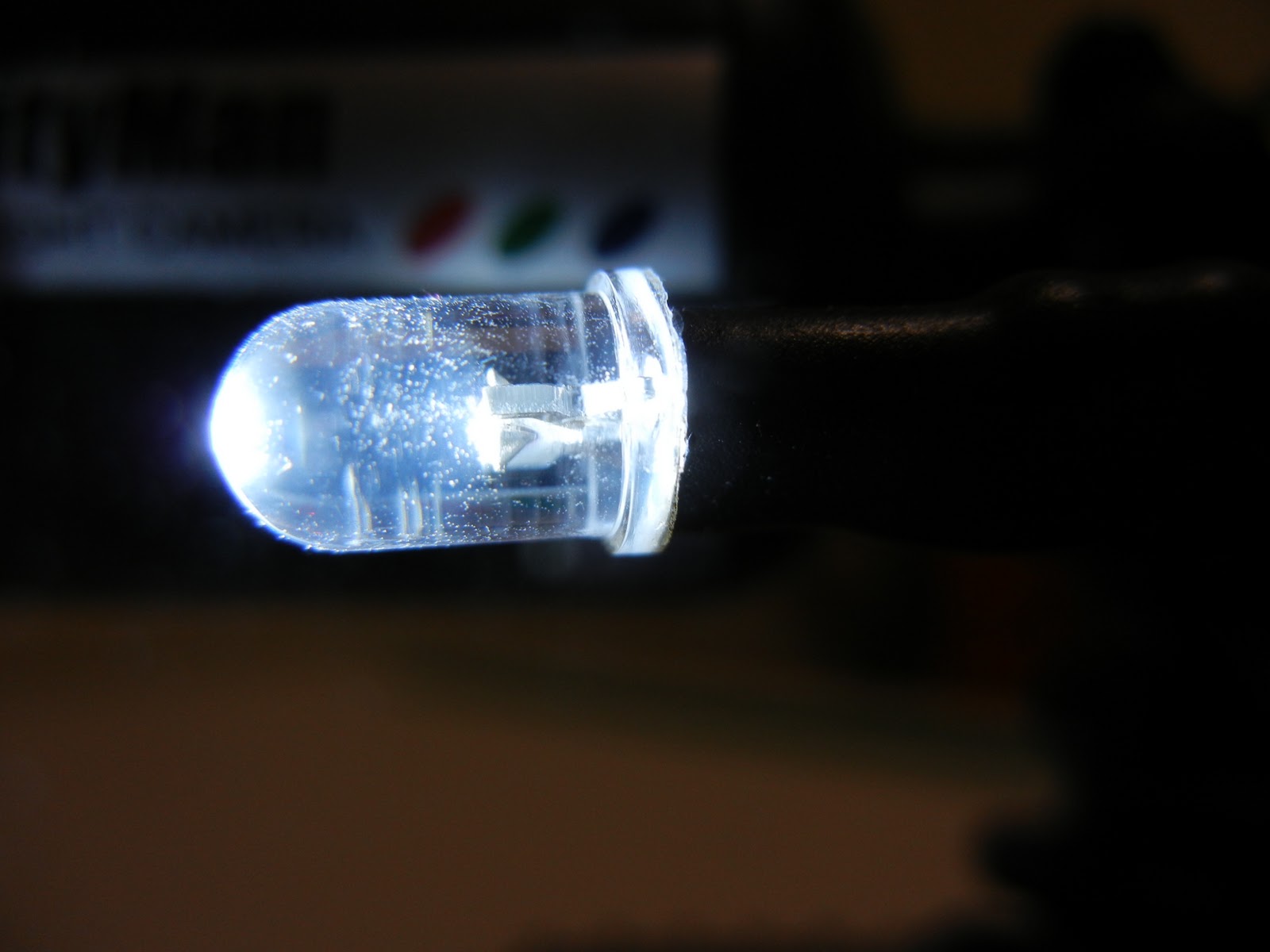
Assembly went smooth except the LEDs weren't working at all. Tuesday night I decided to rip them apart and try to get to the bottom of it before the meeting. Well that didn't go very well and it ended up with just bare wires where the LEDs should of been.


Meeting:
The demonstration at the meeting went fairly well except this time I tried to demo the on-board camera but was unable to get the signal working. Turns out it did work for a second; it should of been on channel 2. Oh well, for next time. I was able to finally show my VB.net application which I use for direct control when on the road or testing.

The rest of the meeting was great and I was able to see a demonstration of a exoskeleton up close and personal. As well as network with other people which is always a highlight of the meetings.


Troubleshooting:

Thursday night I decided I had to get to the bottom of why the LEDs weren't working. I decided that it might be due to the fact that I switched to a 3.3v system and the LEDs had a forward voltage of 3.4v. So on my way home from work, I picked up a bag of assorted transistors from Radio Shack to see if I could figure it out.

After many hours of head scratching, bread board testing, and Googling, I still didn't have it working. I could get the LEDs to dimly light up but not to full brightness. I was at a loss to the problem. Finally I put down my soldering iron and decided to call it a night, which is something that is very hard for me to do. I sleep much better if I can figure out a problem before bed or at least know what I need to do that next day to solve it. Before crashing for the night I decided it would be a good idea to post my problem and get another pair of eyes to take a look. I whipped up a schmatic and posted my problem on the Arduino forum. By the time I went to bed and after some back and forth posting, user CrossRoads, who has been very helpful in the past, asked if my pin was set as output. As I was laying in bed I stepped through my code and I realized that might be my problem. I quickly got up, ran to my computer. Sure enough I checked my setup function where I setup my pins and it was missing. No code to setup the LED pins. Doh! I couldn't believe after all this that was the problem. All in all I still needed the transistors so that I could borrow power from the step-up to have full or as close to full brightness that I could possibly have. CrossRoads also helped with getting my transistors setup with the correct resistor values to obtain close to full brightness. Thanks!

Now with the LED problem solved I could move on to the fun stuff! Most of the base code I had written while waiting for the circuit board to arrive. All I needed now was some tweaks and to write two functions for basic autonomous operation. In the past the HBRC has had some tabletop challenges in which I would have liked to compete in but I didn't have a robot built for that. I figured that the line following sensors could probably detect the edge of the table.


Playing with Autonomous:

Saturday was the perfect day to play with and mount my line sensors. My fiance heartsy was having a crafting day with a friend so this left me to focus on my robot. First thing was to mount the sensors and write some testing code to see how well this would work.


First trial run went very well. The sensors return logic 0 for a black surface and logic 1 for everything else, but if there isn't anything in range to bonce off of it will return logic 0. Perfect! After writing some basic code to check to see if the sensor is returning logic 0, past the edge of table. Worked perfect, well for the most part. I mounted the sensor under the front of the robot which means the robot doesn't have very much time to react. For the most part this works but not if the robot is at an angle in relation to the edge of the table. The robot can stop in a position but due to the weight of the camera, it causes it to fall off the table. Of course I was there to catch it. Back to the bench to extend the sensors past the front of the robot and tweak the code as to have more sensor checks per second. This is one case I really wish the Arduino had more interrupts. The two it does have is taken by the battery alert and the front IR switch. Had I thought this through I would have not had the battery use an interrupt and just poll it every few minutes. This would have freed up one interrupt for the line sensor. Either way I was able to tweak the code to have a reasonable response time. 

With the tabletop mode working so well I decided to write a function for line following mode. After writing a few If/Then/Else statements I had a basic line following algorithm. For the most part it works fairly well as long as there isn't any sharp turns. I want to go back and try to speed up the code possibly by using millis() function instead of delay() which I did end up using for my sleep function. That way I can check the sensors while adjusting my path.


Both functions are setup to run separate from the main loop. This way all of the other functions cease and everything is dedicated to checking the line sensors and reacting accordingly. The modes are set via a command over the serial port. The tabletop mode is stopped by using the reset button and the line following mode is stopped when the front IR switch detects an object. I will probably change the triggers for stopping the modes but this works for now. To speed things up I am not checking for incoming commands.

I found this tiny line follower robot on Hackaday which follows a line very well but uses 8 IR sensors on the front.


If anyone can help with my line following function please post in the comments. I couldn't find any examples, which was surprising. I will post some videos once I get a chance to film them. 


Monday, December 5, 2011

Finally, it has arrived! (Late Post)


It was the afternoon of November 25, we had finished our Black Friday shopping and had finally gained some needed sleep. I was anxiously awaiting for the mail carrier to deliver my order from BatchPCB. I checked the mailbox to find my anticipated package had finally arrived. I hurried inside, ripped open the envelope, and found not one but two beautiful PCB's. Being it the Thanksgiving weekend and wanting to take good pictures, I wasn't able to start using the boards until Sunday evening. Because playing a new Xbox title took precedence. With the weekend coming to a close I had to at least get something completed. My photographer (fiance) was able to take pictures before I started going at it with the soldering iron. 


Here are the boards, untouched:


After testing the board I started assembly:


Completed PCB:


Sunday, November 20, 2011

BatchPCB Windows Gadget

After obsessionally refreshing BatchPCB's stats page I got the idea that a Windows Gadget would be perfect and would let me see the latest stats at a glance. This was my first attempt at a gadget but decided to try my hand at it this past Saturday afternoon/evening. I was supposed to be working on my code for Sbot 1 but wanted to see if I could do it. After lots of Googling and trying various things here is what I came up with. Simple but it works.


You can download version 1.0.0 here:

BatchPCB Gadget


The only limitation is it only shows the first panel. If there are more in the queue like on the weekend or evenings it doesn't show them. I haven't figured out how to search for more results when parsing the site. If you can help let me know.

SparkFun Forum Posting


If you find any bugs or have suggestions, post them in the comments below.

Tuesday, November 15, 2011

Special Post - Life Changing Weekend


I don't usually post about my personal life as this blog was created to document my hobbies and projects but this past weekend warranted a post.

A few weeks ago my partner and I had Veterans day off so we thought it would be a perfect opportunity to getaway for the long weekend. We decided to take a trip to Santa Barbara. During our travels from southern to northern California, we make it a point to stop there. It has become our "spot." We've wanted to plan a weekend trip to the area for quite some time but we never had the time or the funds (robotics add up!). While there, our plans were to do some hiking, wine tasting, and tour the city overall. But I also had another agenda. Something that I had planned for awhile but I just hadn't found the right opportunity. This gave me the motivation to make sure this weekend trip transpired. The best part:  she was planning the trip which gave me the perfect cover! I just had to figure out the rest.


Back at it


After a long break I am back at it and time to make some serious progress, on Sbot 1 anyway.

Since coming back from my Ohio trip, I had yet to come to a solution with Sbot 2, so I decided to take a break from it. Well, a few months have passed and I have returned to Sbot 1. I decided to finalize and polish it as a finished robot.  (If there is such a thing as a completed robot, ha!)

About 2-3 weeks ago, I decided I wanted to learn Eagle CAD so I needed a simple project to get me going. I took a look at my Sbot 1 and decided it could use a custom PCB to remove all the jumper wires that make up the connections now. I figured this would be a simple circuit and would get me familiar with Eagle CAD. Well was I wrong about it being simple! It's nothing complex but I ended up adding more to it. I am really happy with the design. During the process I ended up reevaluating the power system and the whole framework. After doing some research I decided to covert it to a 3.3 volt system instead of 5 volts. Unfortunately this would require basically replacing most of the electronics on the robot. I decided it was worth it and that it would make a really nice completed robot platform. Plus, I can have fun coding.


Tuesday, September 13, 2011

Ti Chronos Airplane Data Logging Results

I am back from my trip from Ohio and I finally have some time to catch up to get settled back in my routine. Part of my trip was to do some data logging with my shinny new Ti Chronos Watch. I thought this would be a perfect first project. I ended up not using the stock data software as it doesn't log acceleration. I used the code and app from here:

http://ruditronics.wordpress.com/2010/11/06/data-logging-using-ez430-chronos-watch/


Windows 8 developer preview (download now)


Windows 8 Developer Preview is available for download now!


From Engadget

Got a brain full of Windows 8? Can't stop obsessing about it? Fret not -- as of 8PM PT this evening (just under eight hours from now), you'll be able to download a copy of the Windows Developer Preview to your 32- or 64-bit x86 machine (no activation required) from dev.windows.com. Sorry, ARM hopefuls! Per usual, we'd recommend doing so on a separate partition (or a spare machine altogether) in order to prevent unforeseen conflicts, and we'd also suggest having a stiff glass of patience waiting nearby. Something tells us Redmond's servers are going to be hammered."
Update: The download is live! Click here to try it out yourself, while the slightly less daring can hang on for our first impressions of Microsoft's latest and greatest once we've installed and given it a try.


I just finished downloading it and I am going to try it in a Virtual Machine. 


Let me know if you are trying it, what you think and where you are installing it.


UPDATE: I have it running in a Virtual Box Virtual Machine set with a 1GB of RAM and so far so good. I just wish I had a touchscreen to try it on. This will awesome to have it running my HP Touchpad! I hope the ARM version can run win32 apps, but probably not. I can set the RAM higher but I wanted to see how well it runs with a 1GB. I install the 64bit Developer ISO. I probably won't right any apps but you never know. 


Thursday, September 1, 2011

Blogging from 37000ft with GoGo Air!

Just wanted to drop a quick post, just to say I have blogged from 37000ft. Currently flying over Utah to Dallas  from San Francisco with a final destination in Dayton, OH.

Thanks to GoGOAir I am able to do this. Their service works pretty well and enjoying it. I do have to say that web browsing is great but doing a speed test not so much. I was getting less then .3Mbps which is nothing compared to normal mobile broadband which is what you are supposed to get. Of course it could be just the amount of people using internet right now. Its a full 737 so lots of people on board.

Currently we are traveling at 540Mph.


I will have WiFi on my second leg and on the return trip if anyone has questions or want me to try anything. I will try some video streaming and see if that is possible but I doubt it, maybe audio will be fine.


Forgive any grammar and spelling errors since I don't have my editor around to check my post.


Thanks everyone for reading my blog and don't forget to follow me.


Edit: Forgot to add the best deal for people who don't fly often is the 24hr pass. Its $12.95 but on sale this weekend for $9.95. So I bought 2 passes.


Wednesday, August 24, 2011

Ti Chronos ez430

Yesterday I received my Chronos sport swatch from Ti. I saw a post on HackaDay about Tideals.com. At half off of the original price, I just couldn't pass up ordering a new gadget to play with. After doing some research before I ordered it, I ended up getting the Ti LaunchPad for $4.30 as well. A MSP430 dev board. For the price, why not? Plus both included shipping.

Here is the LaunchPad:


And the Chronos:

Now just to figure out want to do with them. I started messing with the Chronos last night and it defiantly isn't as easy to get started as the Arduino but I am sure I will get comfortable with it after some time.

I was thinking since I will be flying next week, my first project would be data logging pressure changes during a flight. As it turns out, I can do it with the included software.

Once I get some time I will have to try the "hello world" to get started and familiar with the tools and processes.

So far, I haven't found any sites that provide help with getting started right out of the box and uploading your first code. I want to add some basic stuff while keeping the original in tact. I have my workspace started with the stock code so far. Time to do some dissecting....

If anyone knows of some good sites post them in the comments.

Off to do some coding!

Week of 08/14/2011 & 08/21/2011 - Motor Stuff

On a mission to solve this motor problem I was up late one night doing research. After some calculations and research of different motors I ended up ordering a few.


The difficult thing was finding a motor that was the same size and low power requirements but having more torque than what I had.

Fast forward to this week of 08/22/2011 and my motors have finally arrived. I spent the evening swapping the front two motors and testing the results before I replaced the other two. To my disappointment they seemed weaker than the originals. 

The next day, I decided to put the originals back in. Wow! Such a pain to end up at square one. I ended up breaking 2 tabs, one on each motor. It was frustrating. But as a result, I will be posting a tutorial of how to fix these motors when the tabs break. I was about to put everything away and deal with it another day but after some investigating I figured out a way to fix the motor and make it usable. Should be posting that within the next week or so.

So now it is back to the drawing board to solve my under torque issues. I have some ideas as how to proceed but I might just skip ahead to my custom PCB phase instead. 

  1. I need to do some tests to see if maybe my motors just don't have enough current available.
  2. I could design a custom motor controller with separate power inputs and higher current limits.
  3. I am thinking to look into modifying the current motor controller to allow for separate logic and motor power inputs.

Two and three allow me to remove the step-up convert which would be nice plus better power efficiency.

But after all this, I'm thinking it might be better to skip ahead, go with the next phase and design a custom PCB that includes all parts. 

This would be a PCB with motor controller, Arduino Mega and other shields all in one. Plus a nice signal connector for all sensors. 

Also, this would be my first PCB design and I am looking forward to it; but it would delay a working robot for awhile, at least. 

If anyone has some ideas or can help please drop a comment below. This is really my last problem and the rest is all coding. 

Here is the current thread with more details.


This week I have been out sick and I will be flying to my cousin's wedding next week. Other than my tutorial you won't see any posts until September but I'll still keep in touch via the comments. 


Tuesday, August 16, 2011

Week of 08/07/2011 - Motor Problems and Other Projects

Another week has gone by without making much progress on the SBot project. My primary problem has been getting it to turn reliably. There is seemingly insufficient torque to turn with the weight even with 4 DC motors, but they are wired in parallel in sets of 2. Using the bathroom scale, my robot weighed in at a reasonable 3.8 pounds. There are ways I can turn over a distance but not within a small space which is needed for docking. After some research and posting online, it doesn't seem that my problem is power related even though the LCD does dim when the motors start moving. Disconnecting the LCD doesn't seem to make a difference, so I really need stronger motors.

Last week after having coming to my conclusion about needing stronger motors, I decided to finish some other things on my to do list. One of them being to rebuild my Asterisk PBX. Originally it was a VBox VM running on my computer which was used mainly for free calls via Google Voice. This time I wanted to run it on my VMWare ESXi server using the updated Google Voice calling script. I also decided that I wanted to have a cleaner reliable install to be able to use for more than just myself.

Unfortunately, my VM server can only have 4GB's of RAM but I am no longer running my own email server and therefore have freed up resources to play with. I recently migrated to Google Apps after running my own email server since 1999. It wasn't an easy choice but now it's hands free email.

Using Incredible PBX from Nerd Vittles I rebuilt the PBX from scratch. The nice thing about this build over previous versions is that you don't need an incoming DID. The PBX can connect directly to Google Voice thanks to the Google Talk gateway.

For the most part everything is working and I already have a few extensions running.  Originally I was going to have incoming and outgoing via the PBX on my phone but it really does affect the battery. So I have my Android phone setup to use Internet Calling as an option when placing a call. I also setup my girlfriends' iPad with an extension which works well. It's kind of cool to be able to make calls on the iPad that are completely free.

Overall, I am not sure how practical this will be as a lot of calls I make are free anyway and I usually don't have any problems with enough minutes. Either way there is still the cool factor and a good conversation starter for your geeky friends. Oh and yeah, it's also a very good learning experience.

If you want to try it head over to http://nerdvittles.com/?p=740 and give it a shot. One thing to note is I am using the same Google Voice account as my cell phone since I wanted to retain my routing and people can call my cell causing it to fall back to my PBX if I don't answer. I am still using Google for my voice mail but you could use the PBX. So far I haven't had any problems as mentioned in the guide.

If you have any questions about my setup or getting yours going, free feel to comment and I can try to help.

Have fun making free calls! Don't we all love the internet?


Wednesday, August 3, 2011

Robot Control Web Site

Since SBot 1, I have been working on a web site to control my robot. This way any platform can control it as long as it has a browser. Eventually I may create specific apps for Android/iPhone just for the experience of mobile app development as I have not had the opportunity.


I recently added forms based authencation. Before it would prompt for login. The back end uses Active Directory.
 This is the control site for SBot 1. You can see a tab for JBot1. That is an implementation I setup to use java to refresh the images so they are smoother but doesn't work for mobile.
Control site for Sbot 2 which doesn't have all the controls yet.


I started with the simple ASP.Net example in Visual Studio 2010 and went from there.

The video is shown using an application called Active WebCam from PY Software which is running on my computer. I have two A/V receivers connected to my computer via two USB capture devices. The images are then saved to my web server. I will post some pictures of the receivers soon.

Let me know want you think. Any ideas or improvements would be greatly appreciated!

Week of 07/24/2011 and 07/31/2011

Even though this week isn't over, I still wanted to post my current progress since during the week of July 17, most of my time was spent packing for Comic-Con in San Diego. It was an awesome trip and I will probably post pictures soon. I wasn't able to blog about it or my robot again last week because with travelling, plus that many people at the Con, and lack of sleep, illness struck so I was out sick most of the week.

So far, this week, I was able to make some progress. Me and my girlfriend have started a schedule to get us back into a weeknight routine so that we can work on projects and other to-do's that get set aside.

Last night I decided to work on the website and add video camera control buttons. After a lot of research I was able to add buttons that increment the angle. The thing that made it difficult was to retain the current position during each HTTP post. I ended up using Session State to store the values. This sets the framework for storage other variables for other functionally. In the future I may use Application State so that if more than one user is using it or I come back to the camera it won't jump and instead it will continue where it left off. I will post some pictures of the site so far in another post.

The rest of the week and probably next week as well, I will be adding more commands to the site so that I can start testing remote control from work.

Security Bot 2 Completed Pictures

After my project was posted on Hack A Day I realized I don't have pictures of the completed build. Of course it goes it without saying that it is really never completed. Who knows what we will be added in the next year or two?


 Sensor ouput on LCD

Right: distance sensors and brightness across the bottom.

Left: camera angles and battery levels.

Bottom: temperature and humidity followed but the last spoken text.
View from the rear which includes the IR switches on the left and right.

At the bottom is the DC jack that is connected to the charging rails underneath.

The PCB from top to bottom,

Xbee, Voice, Proto, Mega
Left: shows the microcontroller battery and step-up.
Charging dock using copper straps from the hardware store. Currently temporarily attached.
Bottom of the robot showing the copper charging straps.

Thursday, July 21, 2011

Week of 07/17/2011 Status update of SBot 2

I've decided to set a goal of blogging about my project progress at least once a week. I get so enthralled with code and such that I set aside blogging about it.

Week Status:

This past week was spent working on the serial read and parsing functions and now working on the website.


Next Week Goals:

I have a robotics meeting coming up in one week and a half so I really need to spend the time to work on motor control. Forward and backward works pretty good. I wish the sensor detected objects better but I need to do some testing on the field of view for each sensor. My main problem is finding an efficient way to turn. The impact on how much power I need to turn a certain distance is dependent upon if I am driving the carpet or tile. This is where I am thinking the wheel encoders will help.

I have tired a few ways of turning and haven't figured out the best way. I have tired slowing down the side or the other or reversing the opposite side. Now that I have better batteries I can push more power to the motors when turning. I think another thing that might help is to have individual motor control which I currently do not have. They are wired in parallel. For it's final design, I am thinking of building a high power motor controller myself that can control 4 motors.


Please post your ideas or ways you have tried to have a robot turn that doesn't have steering.

Serial Reading and Parsing

The code for SBot 2 started with playing with the SpeakJet from SparkFun. I used the code example they posted and my code grew from there as I added functions. This lead to some bad code for receiving serial data and parsing it. Since it was based from the example I had added some code to look for a command character and therefore had some duplicated code and bad data handling. For awhile, it was fine and worked for what I needed.

Finally, I was ready to start updating my Robot Web Controller site to add SBot 2 as it was only setup for SBot 1. The SBot 2 has a completely different API. This is where I noticed an odd problem where the robot would parse the command the first time but after that it would be perceived as text to speech. It would work fine if I was connected to my computer directly or talking directly to the XBee. For the website to talk to the robot I am using SerProxy (Tinker's build) to act as a proxy between the serial port and an IP address. This is when I would see this odd bug. After several posts to the Arduino forum and trying different workarounds, I finally just rewrote the function from scratch. This time with the entire scope in mind I was able to correctly write it from the ground up.

My function now reads the entire string and then parses it. In turn I ended up with some other features. Instead of waiting for any character and looking for a CR (Carriage Return) to finish the input I now look for a start and an end character.  This allows for commands to be submitted continuously which solved my odd bug. Still wish I knew what was going on though. Either way it is better and more reliable. I was able to start and finish this last night. Now I can work on the web site and have a functional robot.


I still have more code improvements and function to write but it is coming along.

Here is the link to the thread with the serial problems and code I was/am using.

Arduino Forum

Security Bot 2

After completing my first Security Bot, I had come across the DFRobot 4WD platform. Once viewing some projects made with it, I was inspired for my second creation. This time around I decided to cram as many sensors into it as possible. My goal was to make this my main robot that I could continually expand upon.

I started ordering parts in January mostly from my three favorite sites. Sparkfun, Adadruit, and now DFRobot and DSS Circuits.  I also a ordered a Arduino Mega Protoshield from NKC Electronics. It turns out Adadruit sells the same board. I decided I wanted to make this one more permanent and use the protoshield and solder everything with header connections for the sensors. This makes it much cleaner and easily disassembled.


I had a few parts already and some credit from SparkFun's free day so I decided to build it as a 2nd robot instead of a replacement of SBot 1. Having two robot leaves for some interesting possibilities later.

In order to assemble a working prototype I ended up having to borrow parts form the SBot 1 (Security Robot 1 and therefore it was inoperable for awhile. I borrowed the XBee radio, battery, and step-up converter.

I decided to use the XBee since it is faster at connecting during development. I already have a WiFi Shield from DFRobot ready to swap in soon.

Long story short, I had some power issues and ended up having to have two power systems and therefore that is why I had to borrow parts from SBot 1. During development I saw that Adafruit had some new batteries that can hold more capacity which can handle more current. So I ordered two of them which freed up the others for SBot 1, plus a spare for future projects. I love the two battery setup and things are much smoother with the new Lithium-Ion cobalt batteries. I decided I wanted to have SBot 1 running again since it makes for a great web controlled, long battery life robot. I made one more order from SparkFun for a step-up booster and a few other parts for inventory. I had a hard time finding a step-up that can handle more than an Amp. The SparkFun step-up will have to work for now since it is just enough that can sometimes power the camera. The original step-ups were from an eBay seller in India but they no longer have them listed. I might have to contact him again or design my own for my final design. With the step-up along with the WiFi Shield, SBot 1 is back in service. Later I will swap the radios.

As ideas come to mind and once I add new features to SBot 2, I will be sure to post them here. The last few recent upgrades other than the batteries were two I2C Fuel Gauges from DSS Circuits and a Real Time Clock from SparkFun.

The reason for the RTC came about in trying to optimize SBot 2 to poll the distance sensors faster. I realized some of the sensors don't need to update every cycle. So after a lot of learning and struggling I got the RTC working where it triggers an interrupt every minute to update the non essential sensors. This sped up polling a lot. The RTC will allow for other possibilities down the road as well.

Originally I was going to use voltage dividers to monitor the batteries like I did with SBot 1. For some reason on SBot 2, they were way off and pretty much useless. I think it had to do with having two power systems and trying to monitor them both from the MCU. I came across an article from Hack-A-Day that lead me to DSS Circuits. This site is great as they bring some of the newer IC's to the DIYer. Prefect he has a Fuel Gauge that solves my problem. They are I2C and return a percentage of the batter left. I ordered three of them, two for SBot 2 and one for SBot 1, which I haven't installed yet.

I did run into a problem with being unable to change the I2C address on the Fuel Gauge which until now I had to use a soft I2C. Today, DSS Circuits posted a new product to multiplex I2C devices. Perfect!


Now onto the good stuff...


Here are a list of parts that I have used so far (well, most of the parts):


First order of parts from DFRobot.com. 4WD platform, IR switches, IR distanace sensors, line sensors, Ultrasonic sensor, WiFi Shield, pan/tilt brackets/servos, and miscellaneous cables and brackets.
DFRobot 4WD Robot Platform. Still need to order wheel encoders.

Order from SparkFun which I used my free money from Free day. Includes SpeakJet/TTS/Speakers, LCD, battery, serial motor controller, ICSP pocket programmer, and Arduino Mega 2560.


NKC Electronics Mega Protoshield Kit and some extra hookup wire.


Fuel Gauges from DSS Circuits.


Here are some pictures of the build and how it looks now. (Final pictures and videos to come)

Testing the Voice Shield with TTS soldered on already.

Internals of the base with original battery, serial motor controller, Adafruit charger and 4 DC motors.
Assembled robot base.


 Completed protoshield. I have added to it since.
Shows the 5v regulator from Polulu and TIP120 to control power to the camera. The top left is the Wii Nunchuck connection and the bottom is a MEMS microphone.


Bottom side of protoshield. I tried to make it as clean as possible.I kind of just designed it as I added to it. I wanted to make sure that everything can be disconnected for easy modification and repair.
Top level of robot during testing. Showing the original microphone I was using and the Temp/Humidity sensor the left.
LCD sensor output.
 Initial test of robot.
 Underside of top level. Shows the two rear IR switches and front IR distance sensors. In the middle is the pan servo for the camera.
Some testing after adding a 2nd battery. This shows the two step-up's and the shields. Starting from top, Xbee, Voice, Protoshield, and Mega.
 Internals with wired connections.


 Sensor connections to the protoshield.

Friday, July 1, 2011

HBRC 9th Annual Tabletop Challenge

During the Maker Faire I attended a presentation about ROS, Robot Operating System. During which I heard about HBRC, Homebrew Robotics Club. Finally I had come across a group of other people that worked on robots at home. I attended my first meeting Wed, May 25th.

Here is a link to their site if you are interested.
http://www.hbrobotics.org/

This past Wednesday was 9th Annual Tabletop Challenge and potluck. For the potluck my Girlfriend and I decided to get creative and come up with some sort of robot or Android inspired idea. In the end we ended up with these.


Can you tell what they are? Post a comment below what you think.

Sunday, May 22, 2011

Maker Faire 2011

It's been four years since attending my first Maker Faire, and this year was great! Each year there are a lot of awesome projects, robotics, electronics, DIY, and the like. This particular year was even better since I am now becoming increasingly familiar with DIY robotics. I felt that I was able to relate to a lot of the content more so with having worked on my robotics project. Below are a few pictures and videos of some of the projects I saw at the faire.


Microchip's ChipKit:


Listening to Massimo Banzi (Co-founder of Arduino) and Chris Anderson (Editor and Chief of Wired Magazine)


Surface ocean research robot(not sure of the name):


Google's SKPR bot:


Master Chief:


DIYDrones and their ArduCopter:


Testing driving a Chevy Volt:


My girlfriend learning to solder:


Have you ever attended the Maker Faire or do you know of it? Check out MAKEzine now!

Did you make it this year? If so, what were some of your favorite projects?